2020-11-13
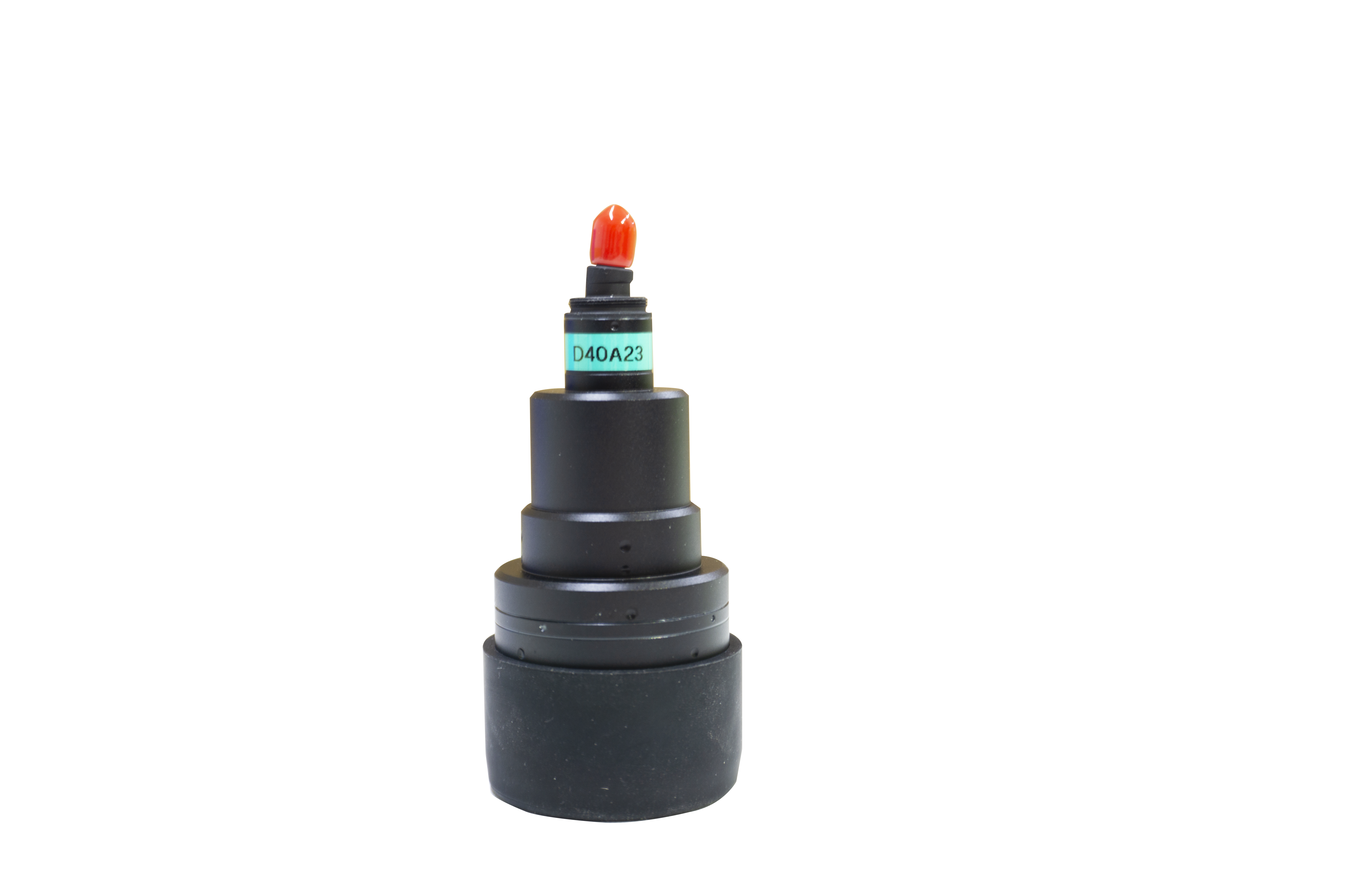
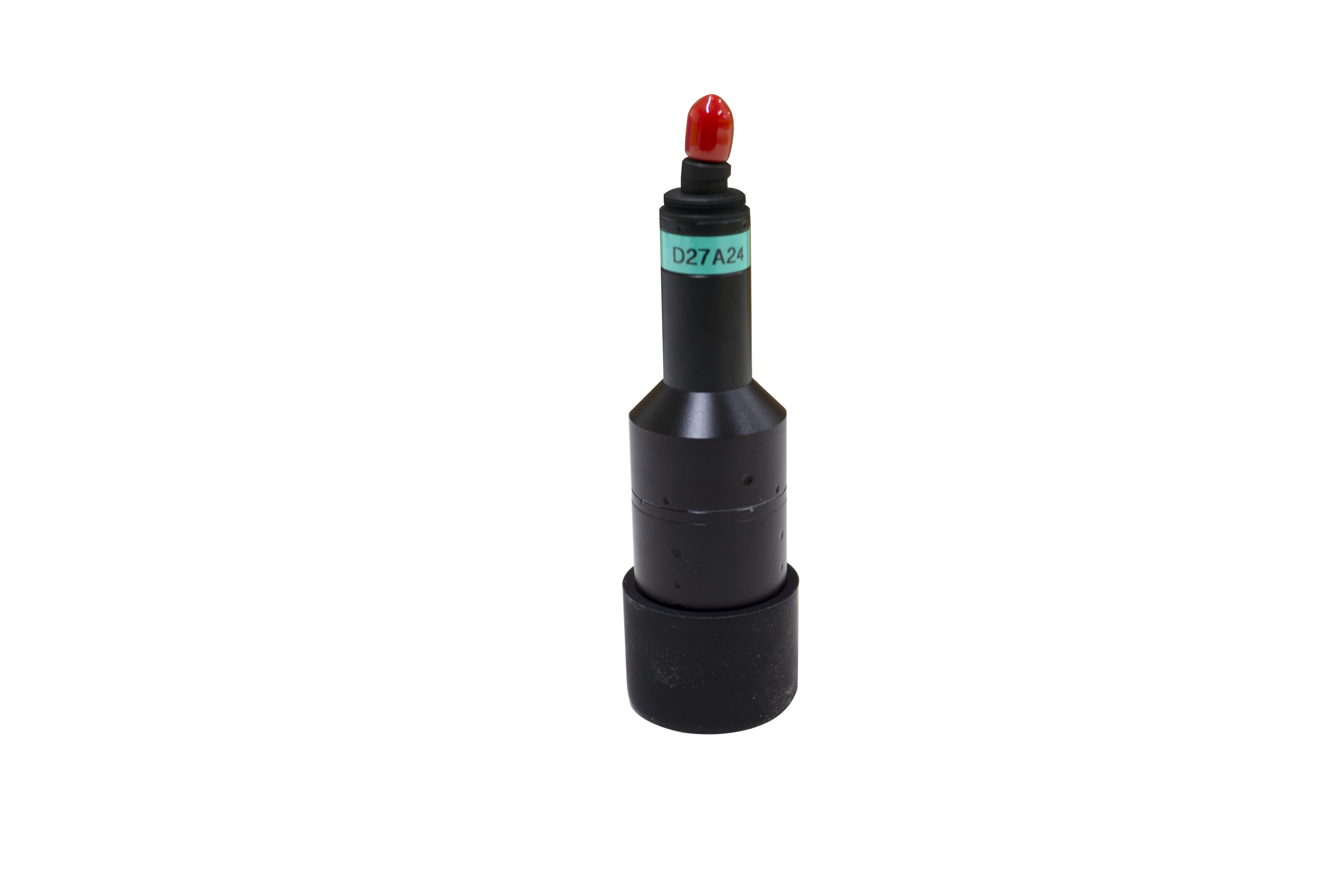
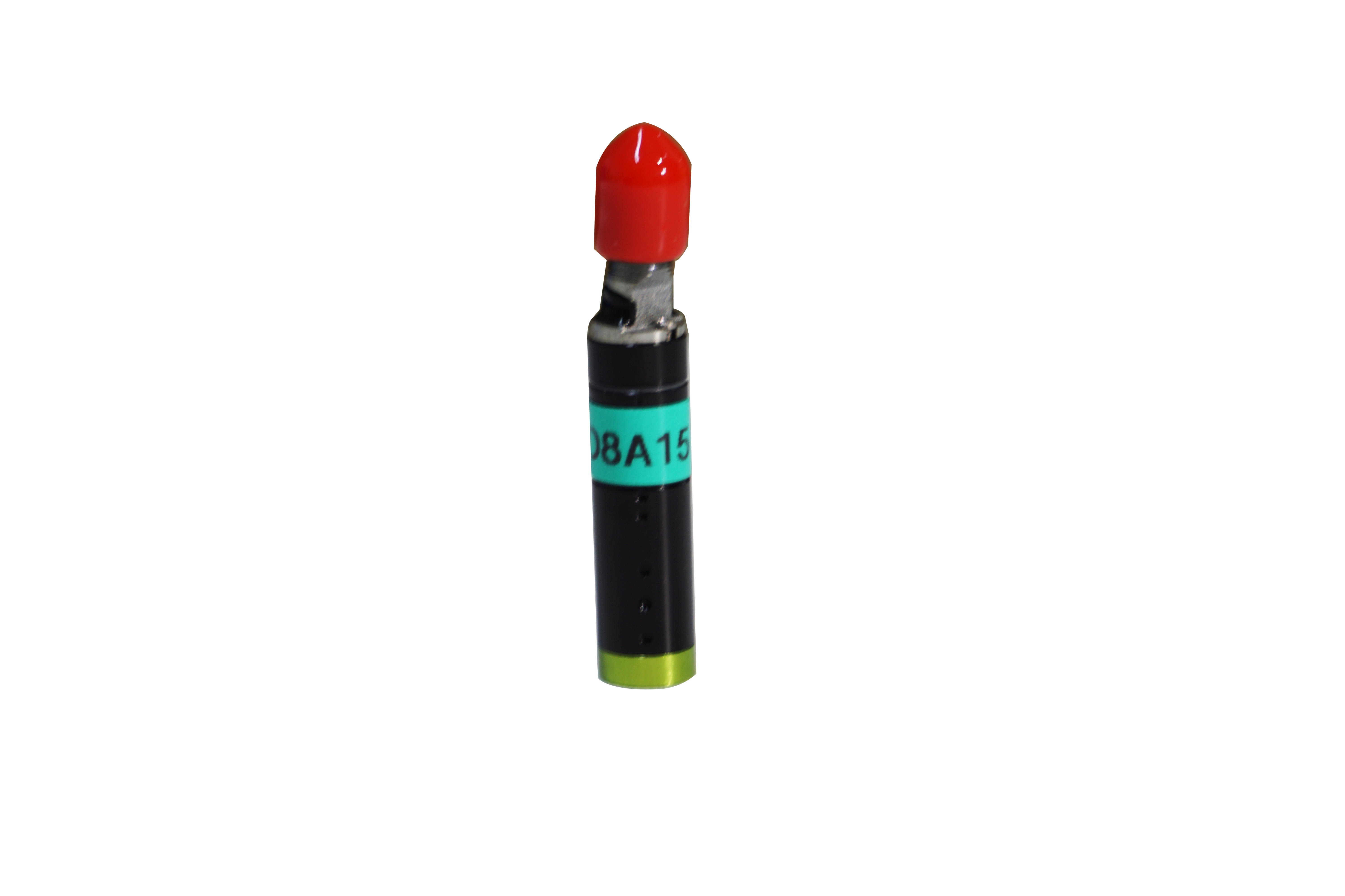
Note on the use of Angle displacement sensor
1. After the sensor leaves the factory, the manufacturer is not responsible for the warranty service for the products that have been dismantled or modified by the user (including tearing off the trademark, processing the shaft housing, loosening the screw, rotating the fastening ring position, etc.).
2. When the sensor is connected to a cable, do not connect incorrect terminals. Pay special attention to the brush terminal (2#), which cannot be connected to the input voltage.
3. When the sensor is powered on, do not use the resistance and current sets of the multimeter to measure the voltage of the sensor.
4. Do not throw the sensor to avoid damage to the leading out terminal.
5. The voltage of the sensor should be within the rated power consumption range. (Note here that the rated power consumption refers to the allowable power consumption of the sensor when the ambient temperature is 70 ° C, and the power consumption should be reduced when the ambient temperature is more than 70 ° C.
6. The recommended current through the sensor brush is 2mA, not more than 10mA.
7. The sensor and accuracy refer to the conformity accuracy of the output characteristics, not the deviation accuracy of the total resistance. The linear accuracy of the sensor adopts independent linearity and depends on the test calculation when the load is open.
Independent linear calculation method: using the method commonly used in the sensor industry, the zero voltage before and after is specified as both ends, and the theoretical electrical stroke and the connection between the two ends are determined as the reference line. Large deviation range (sum of absolute values of positive deviation and negative large deviation; Large deviation and 0 or negative large deviation and 0), as the sensor linear deviation.
8. Sensor with tap, tap width is 4o~5o, the output voltage is basically unchanged in the tap range. The tap is generally used as the starting point or end point of the output, and the tap cannot be included in the theoretical electrical range of the test calculation linearity, otherwise the linear test calculation is incorrect.
9. Although the temperature coefficient of the resistance of the conductive plastic sensor is larger than that of the wireline potentiometer, when used as a voltage divider, the resistance on both sides of the brush changes together under the influence of temperature, and the partial voltage ratio remains unchanged, which has no effect on the linearity of the sensor. (If the resistance value is used as an output, the linearity will change).
10. The installation structure, size and test and calibration point of the dual sensor are generally based on the reference connector (the first connector). Synchronization accuracy generally refers to the percentage difference between the output voltage of the two connections and the total voltage applied at a certain calibration point (the total voltage applied by the two connections is the same), rather than the synchronization error at all test points. Usually the starting point or midpoint (the midpoint of the theoretical electrical Angle) is chosen as the standard point. The synchronization accuracy is generally 1%, which can also be classified as linear accuracy.
